Fixed Axis Rotation
With rigid bodies, we have to examine moments and at least the possibility of rotation along with the forces and accelerations we examined with particles. Some rigid bodies will translate but not rotate (translational systems), some will rotate but not translate (fixed axis rotation) and some will rotate and translate (general planar motion). Here we will examine rigid body rotation about a fixed axis. As the name would suggest, fixed axis rotation is the analysis of any rigid body that rotates about some axis that does not move. Many devices rotate about their center, though the objects do not need to rotate about their center point for this analysis to work.
We will again start with Newton's Second Law. Since this is a rigid body system, we include both the translational and rotational versions. Note that now we have bodies with extent, the location of the acceleration and the axis about which we take moments or calculate mass moment of inertia are important. Linear accelerations are always measured at the center of mass. We will develop several moment equations, depending on the point about which moments are taken.
| \[\sum \vec{F}=m*\vec{a_G}\] |
| \[\sum \vec{M_G}=I_G*\vec{\alpha}\] |
By setting up a free body diagram, determining the equations of motion using Newton's Second Law, and solving for the unknowns, we can find forces based on the accelerations or vice versa.
Balanced Rotation
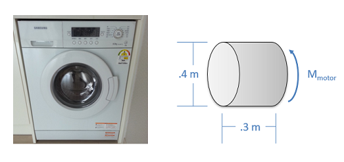
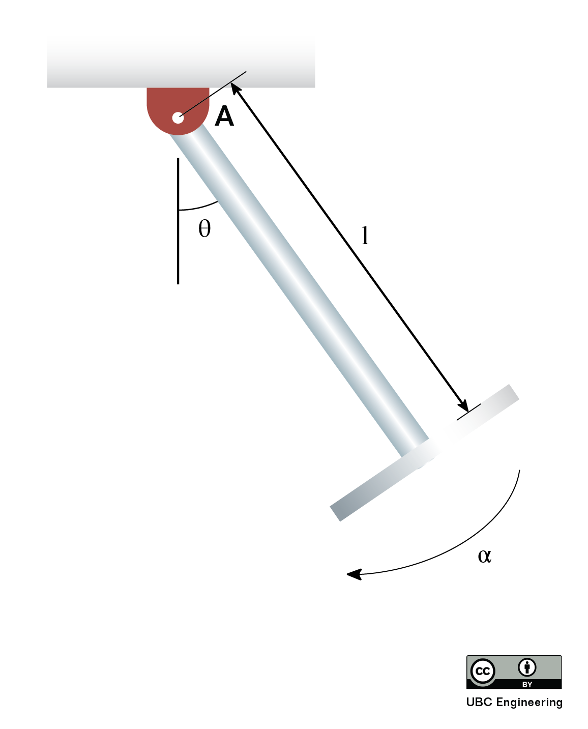
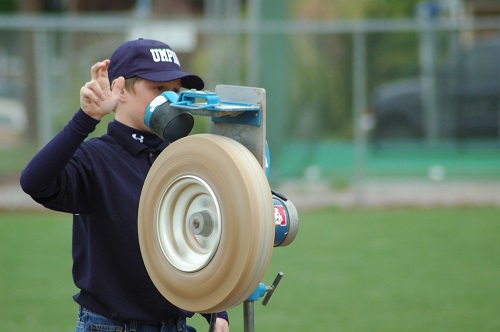
If the center of mass of the body is at the axis of rotation, known as balanced rotation, then acceleration at that point will be equal to zero. The pitching machine above is an example of a balanced rotation, and most fixed axis systems will be intentionally built to be balanced. With the acceleration of the center of mass being zero, the sum of the forces in both the x and y directions must be also be equal to zero.
| \[\sum F_{x}=0\] |
| \[\sum F_{y}=0\] |
In addition to the force equations, we can also use the moment equations to solve for unknowns. In simple planar motion, this will be a single moment equation which we take about the axis of rotation / center of mass (remember they are the same point in balanced rotation).
| \[\sum M_{O}=I_{O}*\alpha\] |
Unbalanced Rotation

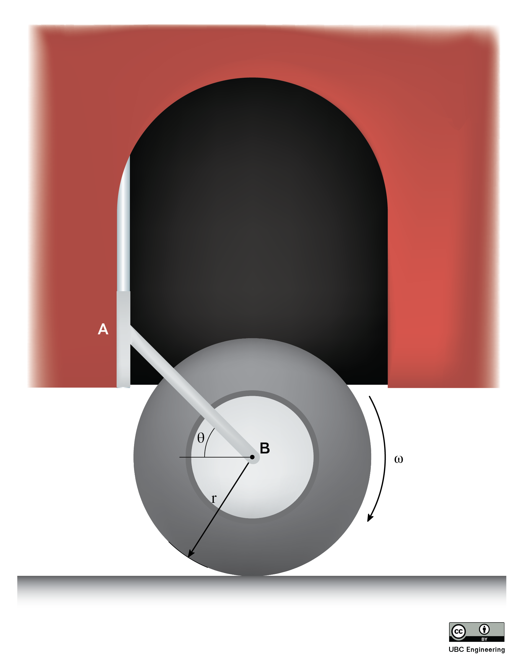
When the center of mass is not located on the axis of rotation, the center of mass will be accelerating and therefore forces will be exerted to cause that acceleration. In perfectly anchored systems these will be forces exerted by the bearings, though these forces can often be felt as vibrations in real systems. Kinematics equations as discussed in the previous chapter can be used to determine the acceleration of a point on a rotating body, in this case that point being the center of mass. After determining those accelerations, they can be put into force equations, either using the r and theta directions, or x and y directions.
| \[\sum F_{r}=ma_{Gr}\] |
| \[\sum F_{\theta }=ma_{G\theta}\] | or |
| \[\sum F_{x}=ma_{Gx}\] |
| \[\sum F_{y}=ma_{Gy}\] |
Note that as the body rotates, the direction of the acceleration and the direction of the forces changes. Also note that the further the center of mass is from the axis of rotation, the larger the mass, and the larger the angular velocity the larger these forces will be.
To supplement the force equations, we can use a moment equation about either the axis of rotation or the center of mass, as these are no longer the same point. Whichever is chosen, just be sure to be consistent in taking the moments and the mass moment of inertia about the same point.
| \[\sum M_{O}=I_{O}*\alpha\] |
| or |
| \[\sum M_{G}=I_{G}*\alpha\] |
More information on how to calculate the mass moment of inertia for a body can be found in Appendix 2.