Finding Internal Forces via Equilibrium Analysis
As a review, internal forces are the forces that exist within a body in order to balance out the external forces on that body. Understanding these internal forces will be essential step towards determining how bodies deform or even break under loading.
To determine the internal forces and moments within a body, we generally have two approaches. We can either split the body into sections and perform an equilibrium analysis to determine the forces and moments at one specific location, or we can use graphical approaches to determine the forces and moments along the length of a body, beam, or shaft. In this section we are going to focus on the first method, which will be the most straightforward method for determining the internal forces and moments at a single point.
Determining Internal Forces and Moments via Equilibrium Analysis
The procedure to determine the internal forces and moments via equilibrium analysis consists of four steps.
- Solve for all external forces.
- Draw a free body diagram of one half of the body, cutting the original body in half at the point of interest.
- Write out the equilibrium equations based on the free body diagram.
- Solve the equilibrium equations for the unknown internal forces and moments.
The first step when determining the internal forces is to solve for any unknown external forces. This is just done using an equilibrium analysis for a rigid body as described in previous chapters, and is necessary because the equations we generate to solve for the internal forces will only just be sufficient to solve for the new unknowns. If we carry forward unknown external forces, we will wind up with more unknowns than equations and the equations will be unsolvable. One shortcut we can take however is that later we will only be analyzing one half of the body, and so we can skip solving for unknowns on the half of the body that we do not plan on using.
Next we will want to imagine cutting the body in half, and we will want to draw a free body diagram of just the one half of he body. Which half you choose is up to you, but the side with fewer external loads on it will make the analysis easier. Make sure you include any external forces that are acting on the chosen half of the body, and we will be adding an unknown normal force, an unknown shear force, and an unknown internal bending moment at the cross section surface.
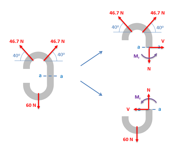
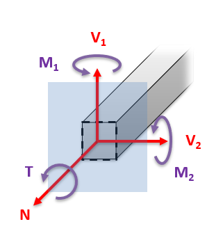
In 2D problems we will always has two unknown forces (normal force N and shearing force V) and one unknown bending moment (Mr). If we are analyzing a 3D system, there will be three unknown forces (one normal and two shearing forces) as well as three unknown moments (one torsional moment and two bending moments) at the cut.
After we get the free body diagram of one half of the body, the next step is to write out the equilibrium equations for that one half of the body. Treat the section of the body just like any other rigid body and set the sum of the forces and the sum of the moments equal to zero.
Finally, once you have the equilibrium equations set up, you simply need to solve them for the unknown internal forces and moments. As long as you have solved for the external forces earlier, you should be able to solve for all the internal forces at this point.