The Impulse Momentum Theorem for a Rigid Body

The Impulse-Momentum Theorem states that the impulse exerted on a body will be equal to the change in momentum of that body. In rigid body systems, this refers to both the linear impulse and momentum as well as the angular impulse and momentum. In equation form, this leads us to out two base equations.

\[\Delta \vec{J} = m \vec{v_{f}}-m \vec{v_{i}}\]
\[\Delta \vec{K} = I \vec{\omega_{f}}-I \vec{\omega_{i}}\]

A few things to note about the equations above when dealing with impulse momentum problems. First is that the above equations are vector equations, and can be split apart into components. For two dimensional problems, we will commonly break the linear impulse momentum equation into x and y component equations, while the angular impulse momentum equation will be about the z direction. Second, the velocities in the linear impulse momentum equation should always refer to the velocity of the center of mass of the body. And finally, for the angular impulse momentum equation, we can take the impulse and momentum about any point we choose so long as we are consistent within the equation. If the impulse is taken about a certain point then the momentum terms must also be taken about that same point. You can see the previous section for more information on angular momentum about various points.

Solving Impulse Momentum Problems:

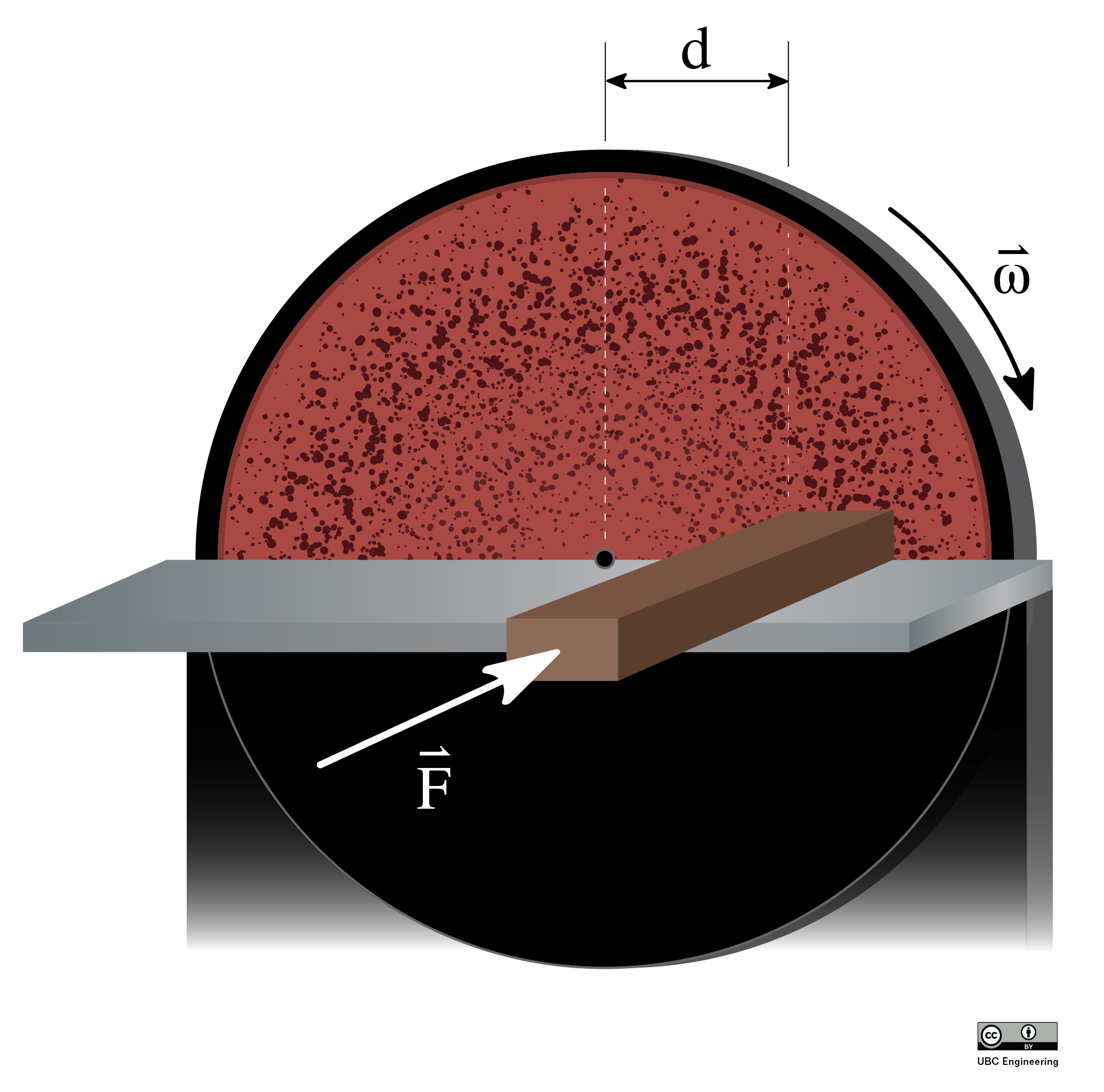
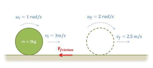
With impulse momentum problems, the best place to start is with a diagram. The point of the diagram is to show the initial state, the final state, and the forces and moments in between causing the change. In your diagram you should show any known masses, mass moments of inertia, any known velocities (magnitude and direction), angular velocities, any forces or moments causing an impulse, and the time these forces or moments are exerted for.

An impulse momentum diagram
An impulse momentum diagram should show the initial and final states, along with any known information about the body in each of the two states. Also shown any forces or moments exerting an impulse between the two states.

After creating a diagram, the next step is to set up your impulse momentum equations. Determine how many equations you are going to use. In 2D problems you have up to three scalar equations, but you may not always need all three equations. You will also need to determine other key factors such as what point you are taking the angular impulse and momentum about. Whatever point you choose, make sure to identify that in your work.

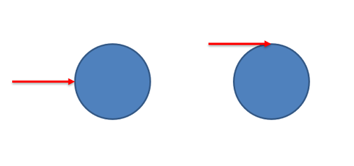
After choosing your equations, plug in any known values for the initial or final states, as well as the impulses acting on the body between these points. At this stage, it is important to remember that moments can come either in the form of a torque directly applied to a body, or as an off-center force causing a linear and angular impulse at the same time.

A force causing a linear impluse and an off center force causing a linear and angular impulse
If we have two identical spheres with forces as shown above, the force on the left would cause only a linear impulse about the center of mass, while the force on the right would cause a linear impulse and an angular impulse.

Finally, the last step is to solve the equations for the unknowns. Make sure you have at least as many equations as unknowns. If you have more unknowns than you can solve for, you may need to use kinematics to relate values such as linear and angular velocity.

Conservation of Angular Momentum:

In instances where there is no external angular impulse on an object, we can see that the angular momentum of the object will remain unchanged. This is known as the conservation of angular momentum, which is simply an extension of the Impulse Momentum Theorem.

\[\Delta \vec{K} = 0 = I \vec{\omega_{f}}-I \vec{\omega_{i}}\]
\[I \vec{\omega_{f}} = I \vec{\omega_{i}}\]

The conservation of momentum is used primarily in two instances. The first is when spinning bodies change shape. In this case the change in shape of the body will usually increase or decrease the mass moment of inertia of the body about the axis it is spinning about. In order for angular momentum to be conserved, the angular velocity of the body must change such that the angular momentum as a whole remains the same.

A figure skater in a spin
Figure skaters will often draw their arms an legs in during a spin to reduce their mass moment of inertia. With minimal impulses to change the angular momentum, the angular velocity will increase so that angular momentum is conserved. Public Domain image by deerstop.

The second instance in which the conservation of momentum is applied is in rigid body collisions. In these cases, forces but no moments will be exerted at the point of impact in the collision. This means that a linear impulse is exerted, but no angular impulse is exerted. With no angular impulse about the point of impact, the angular momentum of the bodies must be conserved about that specific point, and this conservation of angular momentum equation will be an important tool in solving rigid body collision problems as discussed in the next few sections.

Worked Problems:

Question 1:

A miter saw has an operating speed of 1500 rpm. The blade and motor armature have a combined weight of 3 lbs and a radius of gyration of 1 inch.

  • What is the time required for the bearing friction alone (T=.015 in lbs) to stop the blade?
  • What is the torque a braking system would need to apply to stop the blade in just .25 seconds?

Problem 1 Diagram

Public domain image by John F. Looney

Solution:


Question 2:

A bowling ball is modeled as a 7 kg uniform sphere 300 mm in diameter. The ball is released with an initial velocity of 6m/s on a horizontal wooden floor (𝜇k=.1) with zero angular velocity.

  • How long does it take before the ball begins to roll without slipping?
  • What is linear velocity of the ball at this time?

Problem 2 Diagram

Public domain image by Jerry Saslav

Solution:


Question 3:

A wind-chime consists of several slender rods, each suspended on one end by a rope and each with mass m. Consider a singular rod for this problem. As the wind blows, the rod is subjected to an impulse I at its bottom. Determine the vertical location of point O in which the rod appears to rotate.

Problem 3 Diagram

Question 4:

A salmon hatchery has a gate to release water whenever water levels get too high. The gate is normally locked into place, but when the water reaches. The top of the gate, the lock is instantly removed. While the water would flow out of the gate by itself, there is a pump located upstream from the gate to push water forward. The pump is old, so its power slowly ramps up with time. The gate consists of a slender rod in which a 20 kg thin plate is attached. The plate has dimensions a=1.5 m,b=2 m and rotates about the slender rod as if it were a pin. Although there is a seal such that water may not get out, assume the contact between the plate and other surfaces is frictionless. If the gate is subject to water from the pump that applies a force distribution with a magnitude that is related to both the y-coordinate and time dF=(-t(y-2)^2+8t) dy N, determine the angular velocity of the gate after t=2 seconds if the gate initially starts at rest.

Problem 4 Diagram

Question 5:

A city engineer is working on a cargo transport system utilizing gears and racks. She is considering a 30 kg gear with a radius of gyration of kG = 125 mm and a radius of r = 0.15 m. The gear is in contact with a 20 kg rack. If it takes the gear 0.6125 s to reach an angular velocity of ω = 20 rad/s, starting from rest, determine the moment that the gear is subjected to. Assume there is no friction between the rack and the ground.

Problem 5 Diagram

Question 6:

A helicopter tail rotor is used to prevent unwanted rotation of the body of the helicopter when the main rotor changes speed. Assume that the four main rotor blades are each long thin rods with length of 5 m and mass of 30 kg. Assume that the helicopter body has a mass of 750 kg and a mass moment of inertia of 1300 kg-m2 at its center of gravity, located vertically in line with the main rotor. The distance between the main and tail rotors is 6 m.

  1. If the tail rotor is functioning, and the angular velocity of the helicopter body remains at zero before and after the main rotor changes speed from 200 rpm to 300 rpm, find the final horizontal velocity of the helicopter body (starts from rest).
  2. Assuming the main rotor change in speed from 200 rpm to 300 rpm occurs in uniformly over 8 s, find the force exerted by the tail rotor to keep the helicopter body from turning.
Problem 5 Diagram

Solution:


Question 7:

A circular industrial disc sander of radius r = 1m, with a moment of inertia of 0.5 kgm2 is rotating at a speed of 1100 rpm just after being disconnected from power. A block of wood is pushed against the sander with a constant force at a distance of 5 cm from the center of the sander in order to slow it down. If it takes 20 seconds for the disk to come to a complete stop, what is the required force F applied to the wooden block? There are no other losses or frictions in the system and take the coefficient of kinetic friction between the wood and sanding disc to be μk = 0.8.

Problem 5 Diagram